
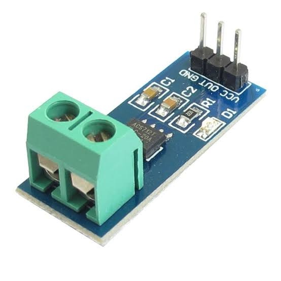
ACS712 Arduino Current Sensor
₨ 300
Technical Specifications:
| Feature | Specification |
|---|---|
| Sensor Type | Hall Effect-Based Current Sensor |
| Operating Voltage | 5V DC |
| Output Type | Analog Voltage |
| Available Versions | 5A / 20A / 30A |
| Sensitivity | 185 mV/A (for 5A module) |
| Isolation Voltage | 2100V RMS |
| Applications | AC/DC Current Sensing, Energy Meters, Arduino Projects |
Description
ACS712 Arduino Current Sensor
ACS712 Arduino Current Sensor is a simplified approach to my prior Instructable regarding measuring AC current with the ACS712 current sensor..
The ACS712 Current Sensor Module is a precision device used to measure AC and DC current using Hall-effect technology. It’s compatible with Arduino, ESP32, STM32, and Raspberry Pi, making it perfect for DIY electronics, energy monitoring, and automation projects.
This module offers accurate and reliable current readings with electrical isolation for safety. Available in 5A, 20A, and 30A variants depending on your project needs.
Key Features:
✅ Measures both AC and DC current
✅ Fully compatible with Arduino and other microcontrollers
✅ High isolation for safe measurements
✅ Analog voltage output – Easy to read and use
✅ Compact and easy to integrate in your circuit
️ Why Choose Robostan?
✅ 100% Original Modules
✅ Bulk Discount Available
✅ Quick Nationwide Shipping
✅ Free Technical Support
Price and Availability:
Price: PKR 300
Availability: In Stock
You must be logged in to post a review.
Related products
-

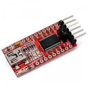
FT232RL USB to TTL Converter
₨ 420 Add to cart -
Sale!
RTC I2C DS1307 AT24C32 Real Time Clock Module
Original price was: ₨ 150.₨ 110Current price is: ₨ 110. Add to cart -
RFID Card 13.56MHz
₨ 50 Add to cart -
Sale!
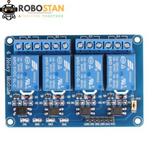
5v 4 Channel Relay Module Relay Board
Original price was: ₨ 400.₨ 360Current price is: ₨ 360. Add to cart


Reviews
There are no reviews yet.